Assembly Instructions
Assembly Instructions
- Marcus Munzert
- Frederic Robra
Owned by Marcus Munzert
Last updated: Sept 15, 2016 by Frederic Robra
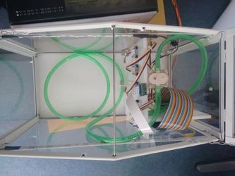
- Build the IKEA SOCKER Greenhouse
- Build the partition walls for the hardware. The wall is approximately at 1/3 of the greenhouse. And consists of a second wall which holds the Raspberry Pi, and on the Backside the PCB.
- Screw the Raspberry Bi to the wall facing the outside
- Screw the LCD on the same side of the wall
- Glue the light strip to the greenhouse. We started at one side of the wall going over the plants to end at the other side.
- Screw the sensors to the wall facing the plants.
- We put the camera on top of the wall facing the plants with 45°. We just cut the wall on the top so the PCB of the camera falls into the incision. Connect it directly to the raspberry pi.
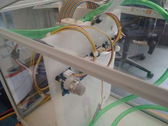
- On the other side of the wall we put the relay, buzzer and the waterpump
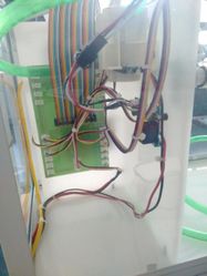
- For the connection we used a PCB which you could also print, but it is also possible to connect all sensors and actors on a breadboard.
- PCB
- Get the layout and let someone print it for you TODO link layout
- Solder all Connectors to the PCB
- Solder the 16 pin socket for the ADC
- Solder the 40 pin connector in the middle
- Screw the PCB to the wall
- You can now connect all Sensors and Actors to the PCB (And even more)
- Digital IO connected to connectors named IO
- I2C connected to connectors named I2C
- Analog connected to connectors named ADC
- The light strip connected to PWM
- Put the ADC on its socket
- Connect the PCB with the rapspberry pi with the 40 pint connector.
- Breadboard
- Connect the ADC to the SPI
- Connect the light strip to pin 16 (PWM)
- Connect the analog sensors to the ADC
- Connect the I2C to the I2C pins
- Connect the digital sensors and actors to the digital pins
- PCB
- Connect the raspberry pi with the power supply either with microusb or with a laboratory power supply on the PCB.
, multiple selections available,